 VANTAGE Windows & Doors
 Roofing Industries
 ALTHERM Window Systems
 Dimond Roofing
 Juralco Aluminium
 SPAX
SPAX


 Prolam
 PGH Bricks
 Metwood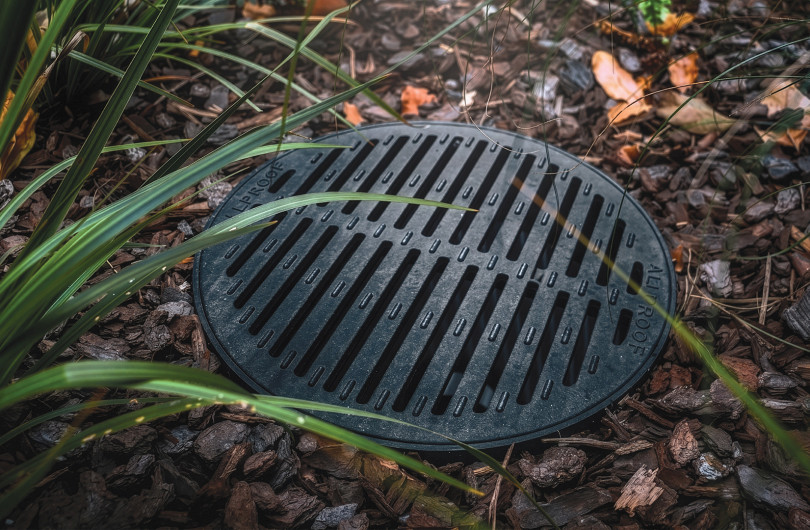







 Allproof Industries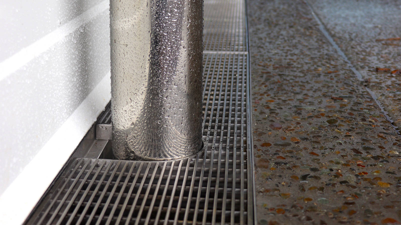
Looking at the overall intention of the detail is important. The channel design serves two purposes. It is a drain, firstly, having the function of removing water from the joinery and building line, then carrying it to the outlet. Making the distance to an outlet under 3.7m will meet the acceptable solution in regard to channel length. (Ch 7.4.2.2 a (iii))
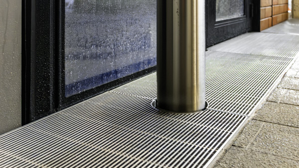
Another intention of the detail outlined in Fig 7.4.2.1 is to create separation between the internal building envelope and external paved area. The 200mm wide by 150mm (min) deep channel creates this separation. This is also described in the MOE Weathertightness Design Guide (ch6.4.1) which states that the channels must be designed as “dry in service”. This means the separation between building elements and the design created to allow the channels to dry, will ensure the internal building elements are protected from external moisture. The use of a grated cover, not solid concrete or timber decking, will ensure that there is good airflow, and the channels can dry out after a rain event. When it’s raining, they are damp. As the event finishes, they dry out protecting the building's elements from being exposed to a damp environment.
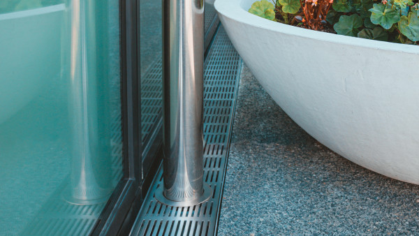
The channels are considered to be surface water drains; this means that the outlets, generally 100mm min, should go via a sump before connection to stormwater system. You don’t need a sump at every outlet, but every outlet must go via a sump. Ch 7.4.2.2 c (ii) requires the design to incorporate an E1 compliant paving solution away from the channels. The paving must fall away from the channel, 1:40 for the first metre. This E1 solution will involve channels and sumps, and these can often be utilised to perform the sump function for the threshold drain also, collecting surface water from the paved area and separating solids from both drainage solutions. Allproof systems do have the ability to add an inline sump, just take care as adding a sump can make the system up to 700mm deep, often causing a clash with structure/footings below the surface. It is sometimes easier to pipe out to a sump elsewhere, as above, in the paved area, or hidden in a garden or out of sight.
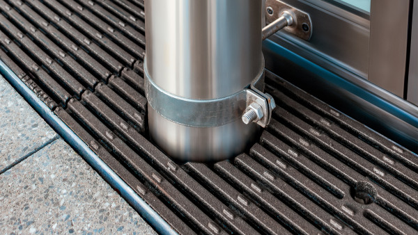
If a downpipe is to be brought through the channel, you must keep the two waters separate. Channels are surface water, downpipes are stormwater. A downpipe cannot discharge into any surface water drain. This is because the type of flow from a charged downpipe may well overwhelm the sump, stir up sediments and send them into the stormwater system. Allproof’s thorough detailing shows that the downpipe can discharge through the channel, not into it. A PVC stump is bought up into the channel, and the downpipe will socket this and bypass the stormwater through the channel, not into it. The GFP grate is cut on site, or Stainless Steel grating is fabricated around the downpipe for a tidy finish.
Ensuring your design meets the acceptable solution can be as easy as reaching out to your trusted, local manufacturer of NZ plumbing, drainage and passive fire products. Allproof’s nationwide support and specification team will ensure that the correct advice is given, and with distribution through the merchant channel, you have a representative in almost every town. Allproof is an NZIA approved CPD provider in Passive Fire and, among other categories, Level Threshold. Please reach out to the team to book your session, and reduce time spent on detailing, and RFI requests.

 Most Popular
 Popular Products