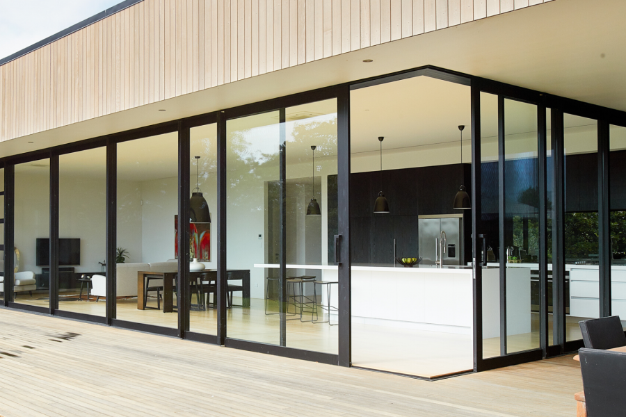
 VANTAGE Windows & Doors
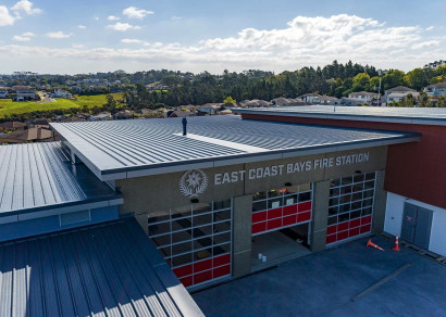
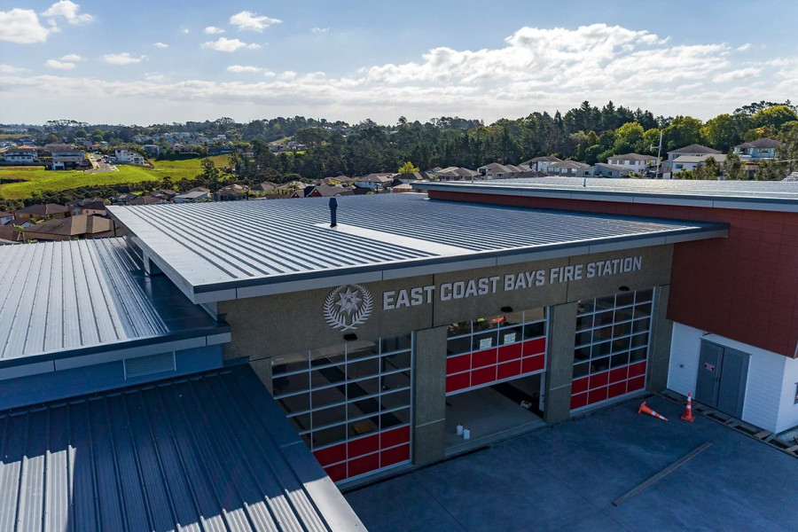
 Roofing Industries
 dormakaba
 XLam Cross Laminated Timber Panels
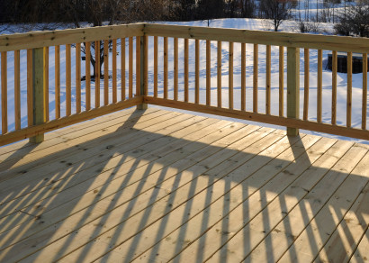
 SPAX
SPAX


 Bates Surfaces
 JESANI
 Aero
Aero


Clause B1 states that buildings should withstand an array of imposed loads, ranging from the structure's own weight to more formidable forces such as water, wind, and seismic loads. B1 also requires resilience against more extreme factors, including fire, impact, and explosions. The building code objective is to safeguard occupants from the building surrounding them while it resists these loads.
Architects and designers must navigate all NZ Code Clauses, whatever materials the building's structure is made from. This brings us to a most dreaded problem in New Zealand and worldwide: structural rot of structural timber elements. This occurs despite regulations being in place due to various factors such as internal and external moisture ingress, inadequate design, poor workmanship, lack of maintenance or untreated timber (TIC).
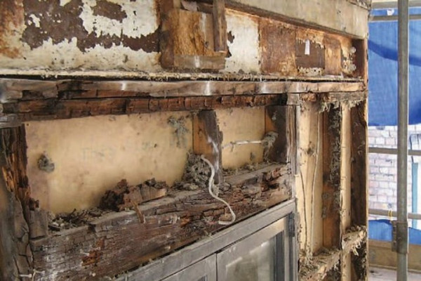
Image 1
These issues are reminiscent of the "leaky building" crisis in New Zealand. While engineers might initially think it's not their problem, mishandling moisture can compromise the 50-year durability required by Code Clause B2, making it a structural issue under B1.
The "1:100 rule," coined by Jon Davies, encourages a thoughtful approach rather than rushing ahead without considering the consequences. One small thing that takes 1 minute to implement on a building project can have an impact for the next 100 years!
For instance, to achieve an R6.6 Insulation value for roofs using the Schedule method of the revised H1 Clause, careful design considerations become crucial, particularly with a skillion roof, as deeper framing is required to accommodate approximately 300mm of fluffy insulation. More framing and insulation increases costs and also alters the rate of vapour movement within the structure. However, taking the time to model the proposed roof thickness will likely yield a better design tailored to climate conditions, resulting in reduced energy demand and a more cost-effective build. Less framing required will equate to a lower cost for materials and installation, and less insulation (the right amount) is less cost.
Decisions regarding the B1 Structure, including frame depth, spacing, and options for internal or external insulation layers, significantly impact heat and moisture dynamics. Therefore, B1 Structure influences B2 Durability, and vice versa, while E3 Internal Moisture influences B2 Durability and affects H1 Energy Efficiency performance. With a holistic approach, we might achieve improved energy efficiency while remaining cost-neutral.
Modelling is essential for such evaluations, and reliable software such as PHPP, or ECCHO can accurately predict energy demand during the design phase.
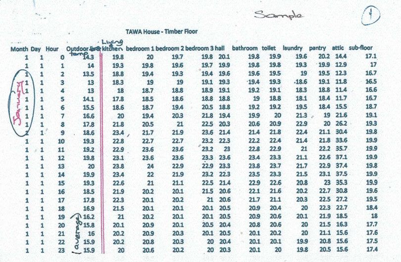
So far, we've discussed roof insulation, but what about other areas of the building? Our analysis of building structures beyond roof insulation shows that excessive timber usage poses significant challenges. While intended to ensure structural integrity, this abundance of timber, as seen in images 2 and 3 below, has spiralled upward. This ‘overuse’ of timber jeopardises H1 Energy Efficiency and exacerbates E3 Internal Moisture concerns. Traditionally, insulation calculations assumed a modest timber % of external walls (around 18%), but recent studies paint a different picture. Beacon Pathway's evaluation of 47 new-build homes revealed startling deviations from these norms. On average, the as-built structures comprised 34% timber, with some reaching as high as 57%. Instead of space to install the expected R2.0 (construction R value), we may end up only achieving closer to R1.0.
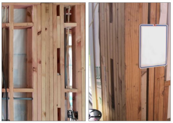
Images 2 & 3
While proposed updates to NZS3604 regulations aim to enhance building resilience, the unintended consequence is an imbalance between structural strength and energy efficiency.
So, how do we overcome these timber ‘overload’ issues? In discussions surrounding building standards and construction practices, several vital considerations emerge. Firstly, whether nogs are required in NZS3604:2011 prompts us to consider the necessity of these elements within the framework of regulatory guidelines. If you are still thinking about it, the short answer is NO, but don’t take our word for it, read this industry expert article to set the record straight.
However, our troubles continue as we seek alternatives, such as steel beams, to extend spans for structural support. A specific challenge arises when steel posts concealed within walls inadvertently create thermal bridges if exposed to outside air temperatures. Steel is much more conductive than timber, leading to increased energy loss and a heightened risk of condensation. Additionally, as insulation requirements evolve, the potential shift towards default 140mm framing in the upcoming NZS3604 update raises concerns.
While such a change may offer improved depth for insulation, feedback suggests it could substantially escalate costs and logistical complexities given the larger dimensions and therefore heavier timber involved. Moreover, the issue of thermal bridging and mould growth warrants attention, as visible stud lines within walls (see image 4) indicate potential moisture-related issues stemming from thermal bridges and lack of ventilation. Addressing these concerns poses a significant challenge, especially amidst promises of warmer, drier, and healthier buildings set against increased insulation requirements and changing climate zones.
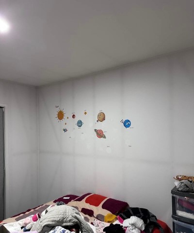
Image 4 — If you can see the stud lines, you have a problem!
To compensate for reduced insulation space, a 45mm internal service cavity can be introduced, either alongside 90mm framing (resulting in a total of 90mm + 45mm) or in conjunction with 140mm framing (resulting in a total of 140mm + 45mm), for colder climates where additional insulation is modelled (see image 5).
An insulated service cavity addresses insulation concerns and offers a practical and economical means of mitigating thermal bridging issues. Furthermore, this approach provides an opportunity to tackle the challenge of steel posts within walls by integrating them into the service cavity, minimising thermal bridging effects.
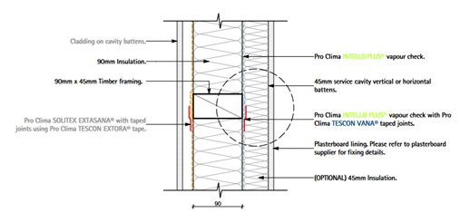
Image 5
Another practical approach to addressing thermal bridging issues without compromising the structure is using exterior insulation, which could be called a 'warm wall.' This is similar to a 'warm roof,' where insulation is placed outside the structural frame. In this setup, as depicted in Fig 1 below, insulation is installed as a continuous blanket outside the structure, eliminating the need for insulation between frame components. This external insulation configuration means better performance with the same amount of insulation simply because it is continuous. This strategy is particularly beneficial for Light Gauge Steel (LGS) frames (Fig 2), where insulation performance is affected by steel conductivity. By situating all insulation layers outside, the structure effectively becomes 'warm’. Fig 3 illustrates a similar concept with a mass-timber wall, such as Cross-Laminated Timber (CLT), where insulation is placed externally to achieve a 'warm wall' effect.
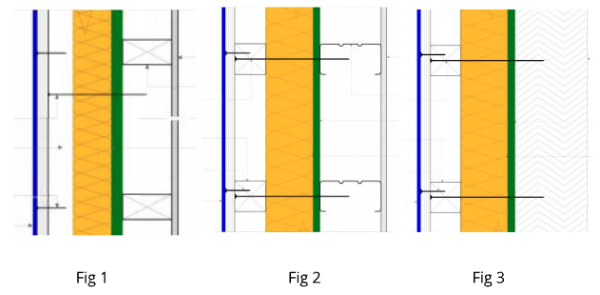
Image 6
There are still some challenges with improving the performance of our thermal envelope. A common issue involves the proximity of hold-down bolts to the slab edge and how to insulate the slab effectively. This topic remains under ongoing discussion within the construction industry (see images 7 and 8).
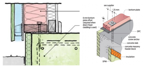
Images 7 & 8
And let's not forget the Corners. We've urged Frame and Truss manufacturers to collaborate with designers to implement better corner solutions. While this approach may not save time or materials, it significantly enhances the building's thermal performance. One solution gaining traction is the adoption of California Corners (see image 9), which allow for increased insulation while maintaining plasterboard fixing points.
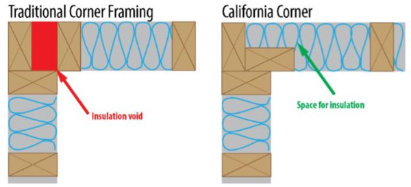
Image 9
Additionally, corners pose geometric thermal bridging challenges, highlighting the broader implications of this issue in building design and efficiency. You can find these details in the Passive House Design Guide.
As we move through the design problem areas, kitchens and bathrooms pose unique challenges due to the convergence of building elements and moisture issues. In these spaces, condensation often forms due to thermal bridges and high humidity. A specific example from Cheltenham Beach, Auckland, illustrates the problem (see image 10). Additional framing installed for various utilities including supporting support leave little room for insulation, further exacerbated by poor installation.
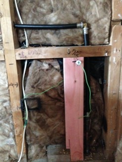
Image 10
While structural integrity remains intact (B1 Structure), moisture-related issues will impact durability (Code Clause B2). This again underscores the interconnectedness of structural and durability considerations.
However, solutions exist, as outlined in a recent EBOSS article. So, what are our options to fix this? We could implement an internal service cavity to separate utilities from insulation or place insulation outside the building structure —and we may get a better building and improve performance. Who would have thought?
If you're an engineer reading this article, you'll likely utilise simulation tools for structural analysis and planning. The beauty of simulation lies in optimising rather than maximising the structure. The same approach can be made with hygrothermal software tools.
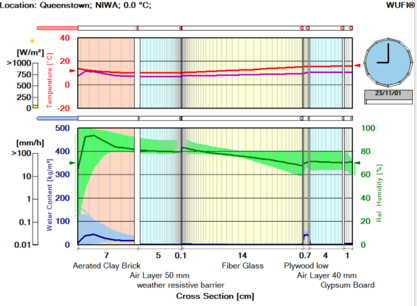
Image 11
Simulation tools like WUFI hygrothermal analysis (see image 11) enable designers, engineers, and building enclosure experts to test proposed material layups and their interactions with local climate conditions such as rain, wind, and sun on the outside, as well as heat and moisture from the inside. They allow for material optimisation and avoid poor combinations at the design stage. Importantly, simulation costs will always be lower than the 'build it and see what happens' approach, providing a cost-effective solution.
For more information or a complete recording of our first Knowledge Zone class, “Cracking open the Code: B1 Cornerstone”, visit www.proclima.co.nz

 Most Popular
 Popular Products