 VANTAGE Windows & Doors
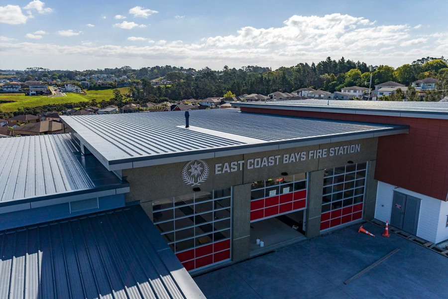
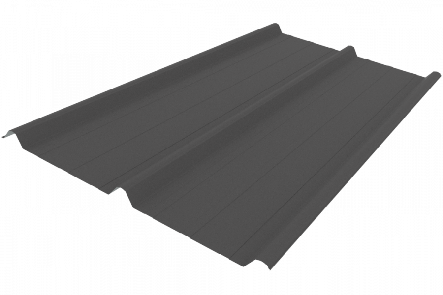
 Roofing Industries
 dormakaba
 XLam Cross Laminated Timber Panels
 SPAX
SPAX


 Bates Surfaces
 JESANI
 Aero
Aero


In this situation, the building plans indicate the location of the floor space provided for electrical services. The electricians are well aware of exactly where the distribution boards will be mounted on each level. Provision is made for single phase power supply into the building and a route for these cables to follow to these boards. We find the number of cables reduces as they go up the building, yet often no provision is made for floor penetrations.
We then find the small cables (TPS) running out of the distribution box, down the corridor, through fire baffles, are clustered in huge bundles. They are then peeled off into each apartment, or fire cell, through a fire wall. This is subject matter for a blog post to follow.
The electricians get the construction project manager to have holes core drilled in the floor for the power cables to pass. The location of these holes is often not given much thought other than the shortest route between two boxes.
What Could Possibly Go Wrong?
All too often, we are called to site when the realisation dawns on the project managers that they are not going to get PS4/construction monitoring sign-off on the electrical passive fire installation.
Appendix C of Acceptable Solution C/AS4 section 5.1 Fire resistance refers:
- C5.1.2 refers: “Fire stops shall be tested”
- C5.1.2 a) refers: In circumstances representative of their use in service, paying due regard to the size of the expected gaps to be fire stopped, and the nature of the fire separation within which they are to be used, and
- C5.2.1 b) refers: In accordance with AS 4072 Components for the protection of openings in fire resistant separating elements – Part 1: Service penetrations and control joints.
- Acceptable Solution C/AS4 section 4.4 refers “Fire stopping”
Fire Stops
- 4.4.2 refers: Fire stops shall have an FRR of no less than that required for the fire separation within which they are installed, and shall be tested in accordance with Appendix C C5.1 (see above)
- 4.4.3 refers: Fire stops and methods of installation shall be identical to those of the prototype used in tests to establish the FRR
- 4.4.4 refers: The material selected for use as fire stops shall be approved for the type and size of the gap or penetration, and for the type of material and construction used in the fire separation.
The NZBC requires that all fire stops must be tested. The test standard is AS1530.4
The simple answer to the question, 'what could possibly go wrong?' is compliance!
What is Most Commonplace?:
- Holes are the wrong size for compliant products
- Holes are in the wrong position
- Wrong service in the hole
- Structural Engineer says, “no more holes!”
- Re-works
- Rectifications
- Need for “Alternative Solutions” leading to non-compliant installations
Consider the Following:
- Cost of compliance failure
- Cost of arguments/confusion/frustration and the time wasted looking for solutions
- Cost of labour waiting for decisions to be made
- Cost of re-works and rectifications that may not be compliant
- Cost of repeat construction monitoring
- Cost of engineering an alternative solution and getting council to sign-off on it
Forethought and Coordination
Building Consent Authorities (BCAs) are now moving toward the position of only being willing to consider an alternative solution in specific circumstances, including where it can be demonstrated that there is no fire stop product or system readily available on the market that complies with AS4072.1.
By having the project managers and the trades more aware of the passive fire compliance regime, encouraging discussion and consultation before simply cutting an arbitrary size, randomly located hole in the floor (with scant regard for the structural integrity of the concrete building element), much of the confusion/frustration can be circumvented.
There are metal transit boxes, designed to accommodate a wide range of services, including continuous runs of cable trays up through the floor slab. These are easy to mount/install and cost effective — IF the hole is the right size and the correct position. The BOSS range of cable transits are compliant and would eliminate much of the indirect cost implications associated with getting it wrong the first time.
A Simple Fix
In consultation with the structural engineer, architects can design both tilt slab wall and floor slabs to incorporate a slot for the installation of a compliant metal cable transit or a single point of entry, multi-service, FyreBox.
The cost of core drilling, and the risk of getting it wrong, is eliminated by simply locating sacrificial boxing in the correct position and at the right size when the concrete is poured. Once set, the sacrificial boxing can be removed, exposing the void in the slab. The hole created should be the right size and in the correct position for the services to be run (installed) and for the metal transit device to be fitted.
Potter Interior Systems is the NZ distributor of BOSS / Abesco range of cable transits. Arrange for an onsite illustration of these transits today by calling 0800 768 837.

 Most Popular
 Popular Products