 StopDigging!
 VANTAGE Windows & Doors
 Roofing Industries
 Cabot's
 dormakaba


 JESANI
 Juralco Aluminium


 Allco Waterproofing Solutions


We are constantly asked to explain the provision of containment pressure to maintain the effectiveness of bentonite tanking membranes. Allco contracted a local Geotechnical company to provide a report on an application to a vertical retaining wall under both static and seismic conditions.
The required containment pressure is taken from the Swelltite Product Manual (Page 3 – Backfill / Technical Material Requirements), which indicates that a minimum pressure of 20 lbs/ft2 (0.95 kN/m²) is required. A copy of the manual, including the relevant page showing the requirement for this pressure can be provided to anyone who wants to see it, likewise it can be downloaded from our website.
Containment Under Static Conditions
The containment pressure on the rear face of a retaining wall is provided by the horizontal soil pressure. This is determined by the active soil pressure, which is the lowest theoretical pressure that can apply to the wall.
For a backfill material with an angle of internal friction of nominal 30 degrees, the coefficient of active earth pressure (Ka) is 0.33. Based on the calculations, the required lateral earth pressure of 0.95 kN/m² is reached at a depth of 0.18m below ground surface.
The shallow depth requirement to achieve the containment pressure suggests that compaction of the backfill is theoretically unnecessary. However, to allow for normal construction tolerances and variations, we recommend that the backfill adjacent to the wall is lightly compacted into place using a small plate compactor or similar to a nominal depth of approximately 0.5m below ground surface. This will ensure that there are no loose zones that could compromise the containment.
Containment Under Seismic Conditions
Under seismic conditions, any loose sand or sandy silt below the water table may be subject to liquefaction. It must be noted that any soils above the water table will not be subject to liquefaction. When the soil liquefies, all of the loading is taken by the porewater (ground water). The lateral loading on the wall then becomes truly hydrostatic. Based on a hydrostatic load from the groundwater, the depth of water required to maintain the containment pressure is only 0.1m. In addition, the weight of the non-liquefied soils above the water table will act as a surcharge on the water column. This will ensure that the required lateral pressure of 0.95 kN/m² is maintained throughout the seismic event by the action of the water pressure.
Lateral loading on the membrane by the non-liquefied soils above the water table is maintained as for the static condition.
Summary
The containment pressure required to support the Volclay waterproofing membrane against the face of a retaining structure is 0.95 kN/m².
Under static loading, the required pressure is obtained from normal soil loading from a depth of 0.18m below ground surface. Irrespective, light compaction of the backfill material against the structure face over a nominal depth of 0.5m is recommended.to compensate for normal construction irregularities.
Under seismic loading, if the backfill soils liquefy, the lateral loading becomes hydrostatic. A water depth of 0.1m is required to ensure the requisite lateral containment pressure. Surcharge from the non-liquefied soils above the water table will ensure that a lateral pressure exceeding 0.95 kN/m² is maintained at all times. Containment Pressure Requirements 7509-1 Volclay Waterproofing Membrane 15 November 2013 3.
The above confirms that the containment pressure required to support the Volclay waterproofing membrane is available from a depth of only 0.18m below ground surface.
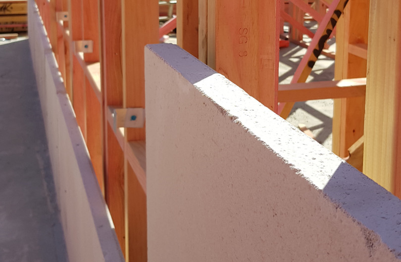
Backfill Requirements for Volclay
The backfill requirements for Volclay tanking membranes; there are to be no voids in the backfill, this is regardless of the type of backfill material being used to confine the membrane. How this is achieved is the contractor’s responsibility. If building above, then the top 500mm must be compacted with a walk behind vibratory compactor or mechanical soil compaction device to the extent that foot traffic on the lift does not leave indentations greater than 12mm. Engineering backfill requirements take precedence for floor substrate. Care should be taken to ensure that the compactor does not touch the waterproofing membrane. External walls will vary as to final topping.
Hydrostatic Conditions – Contact Allco If Unsure
Under hydrostatic conditions a good compactable product is to be used to achieve good confinement of the membrane such as GAP40 with fines. Backfill is to be compacted at 300mm lifts. Protection is required with either 3.3mm Corflute or 6mm fibre cement board.

 Most Popular
 Popular Products