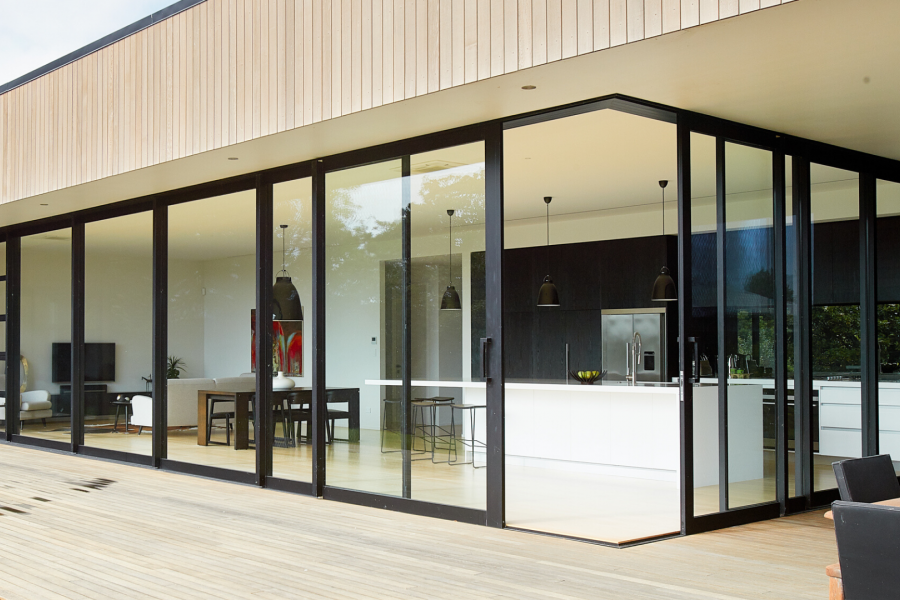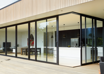
 VANTAGE Windows & Doors
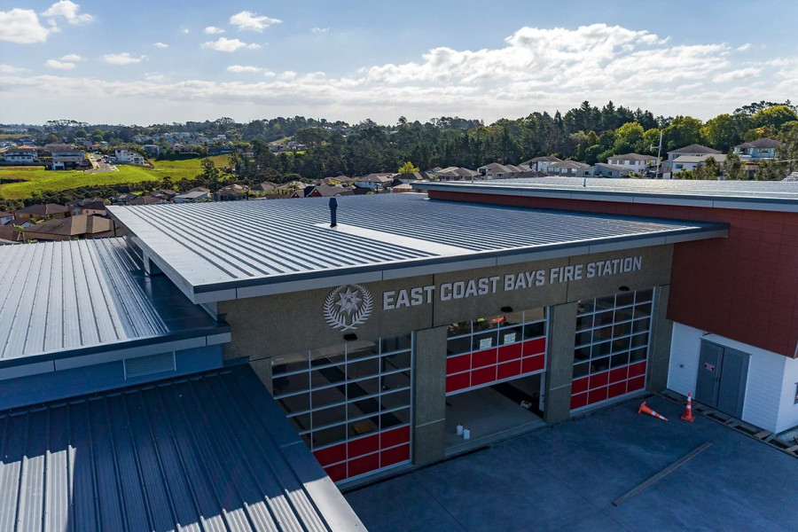
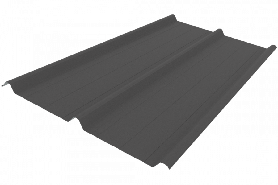
 Roofing Industries
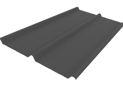
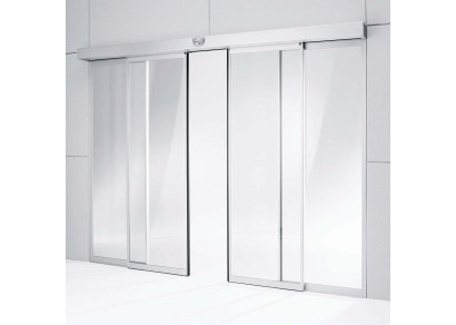
 dormakaba
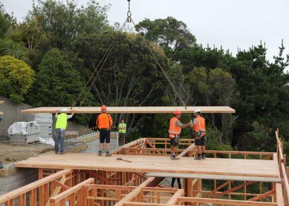
 XLam Cross Laminated Timber Panels
 SPAX
SPAX


 Bates Surfaces
 JESANI
 Aero
Aero


Servicing surface water demand at a garage door can sometimes be linked to inaccurate detailing, or alignment with the incorrect acceptable solution.
E2/AS1 states in chapter 9.1.3.4 requirements for meeting the acceptable solution at a garage door. The main items are the 50mm set down from internal slab to external surface, showing a rebate and ramp down to the exterior paving. With a sealed base to the garage door, this is the beginning of a compliant detail for garage door opening.
The above chapter also mentions “provision to drain water away at the opening”. This is where often selections are made beyond the acceptable solution. Sometimes details closer to chapter 7.3.2.1 (Ground Floor Level Access – Concrete Slab) get used here, suggesting the requirement for a 150 x 200mm channel, falls, minimum lengths etc. This is incorrect, as ch 7.3.2.1 is only relative to pedestrian doors, and garage entries as mentioned above are covered elsewhere.
The provision to drain water away at the opening can be met in several ways:
Falls in paving
Placing the concrete or paving to fall away from the opening and then collected by a sump in the drive is the most commonly used solution. This removes the added cost of drainage at the door and combines the E2 (internal moisture) and E1 (surface water) solutions together. A round plastic pit with cast iron grating also provides most vehicle loading requirements.
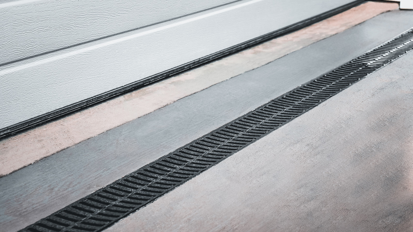
Installing a surface water drain — drainage channel
If the falls as above cannot be achieved, for example if the drive slopes toward the door, then provision to drain water away can be met by installation of a three-sided channel drain. This would be designed to meet E1 surface water requirements, which in turn will meet the E2 solution. There are a few notes here to ensure that your install is both functional and durable/ fit for purpose.
Installation of channel drains are an effective way to manage surface water, with various selections in channel type and grating. These channels should be installed offset from the garage slab to allow the channel to be encased in wet concrete to ensure the loadings can be distributed into the concrete encasement. Butting the channel against a dry slab edge will not achieve this requirement. The encased channel will provide the rebate in the slab to carry water away and support for the grates to be housed, ensuring a durable install. The outlets from this channel will need to go via a sump before entering the stormwater system. This can be achieved with an inline sump to reduce the visual impact of the cess pit, or this outlet could be piped out to a sump elsewhere. Possibly further down the drive as previously mentioned.
The selection of channel drain system will be influenced by the demand the surface will see. A calculation of rainfall demand based on an event, normally 1:50 years, will give a flow rate that must be achieved. Aligning this with outlet pipe sizing and flow rate testing, the designer will be able to confidently select a system.
Allproof designs and manufactures surface water drainage solutions to meet a wide range of demands and install locations. Along with flow rate testing and demand calculations, they can assist with solutions and specification of the correct product. This will ensure less RFI requests and confidence in meeting the requirements of acceptable solutions.

 Most Popular
 Popular Products